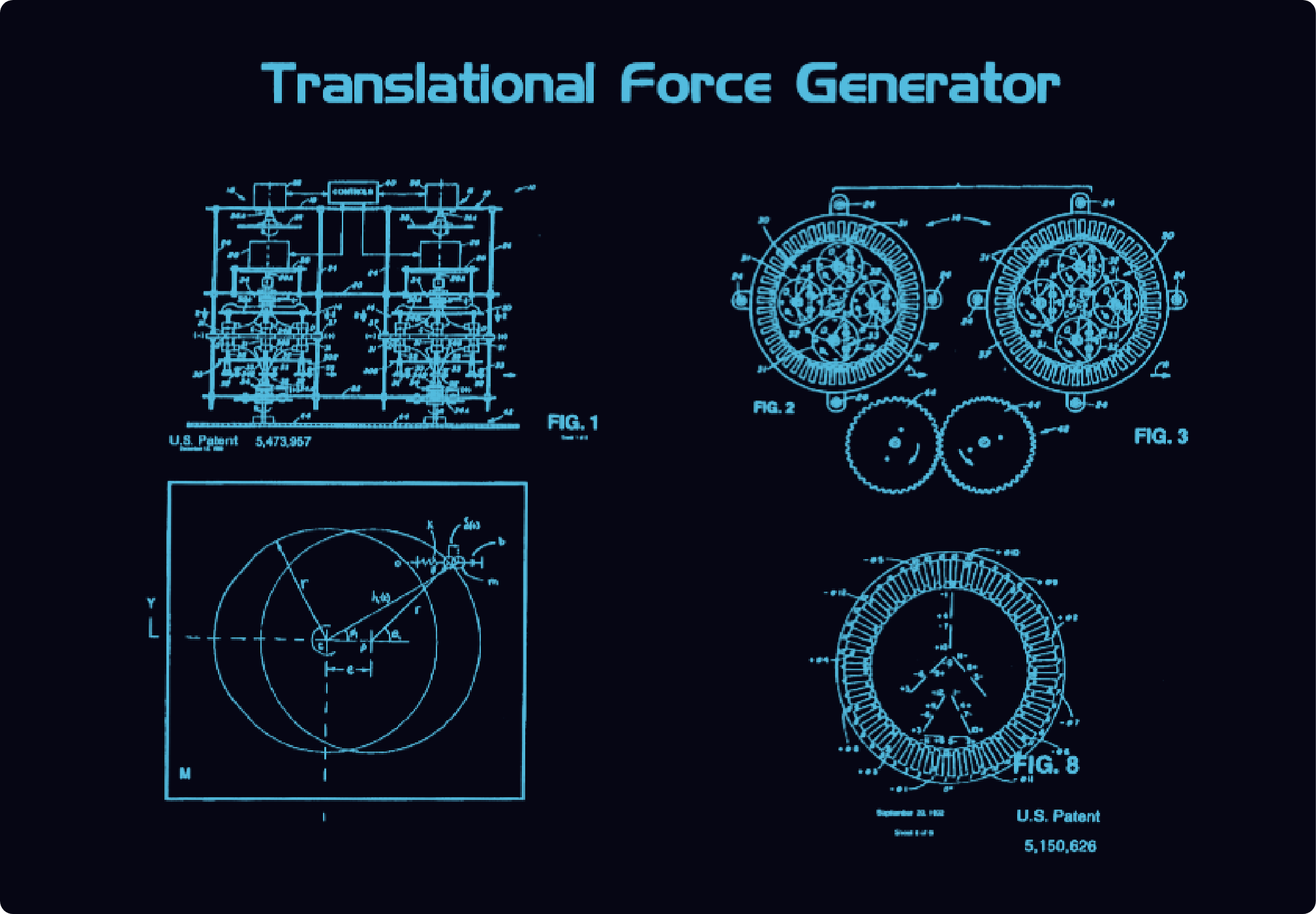
Translational Force Generator-Direct Current system. FIG.1 displays 2 each eccentric mass load systems direct current Quadrupole Systems. FIG.2 displays the polarity on the stator wall and the polarity on each Armature. FIG-3 is the timing gears to keep the eccentric mass loads timed together as one is rotating clockwise and the other eccentric mass load system counterclockwise to keep the eccentric mass load in this drawing to the right in this drawing. FIG.8 is an electrical wiring diagram that is a 12-lead delta Y for the Stator Walls. The square box on the bottom left area of this page displays the eccentric mass load upon the center axis of rotation mathematically.